





Product Overview

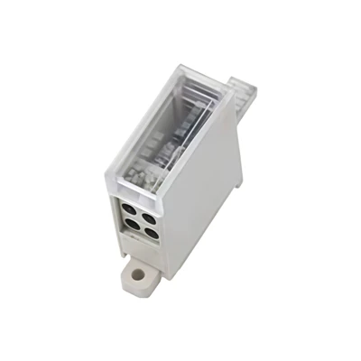
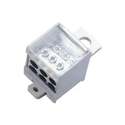
The RCCB Matching Terminal 100 Type is a load-side connection block built around the terminal geometry a 100-frame residual current device already has: the standard 18 mm per-module DIN pitch, the 2P and 4P body widths, and the screw positions the breaker itself comes with.
The reason a matching block is worth designing at all is that an RCCB does not measure current the way a miniature breaker does. Its sensing element is a toroidal transformer, and every protected conductor has to pass through it.
Phase out and neutral back, both inside the window, and the two currents cancel. Take the neutral return from anywhere else and the device reads the difference as a residual current, clears a healthy circuit - or, worse, masks a genuine fault when two wrong paths happen to cancel.
So the value here is not extra ways. It is keeping a phase and its own neutral together on the load side of the device's neutral pole. The block lands on those terminals, spreads them into an ordered row, and leaves the electrical pair inside the transformer window where the trip decision is actually made.
Mechanically it is a tinned copper conductor set in a PA66 housing: 10–35 mm² copper on M6 clamps torqued to 4.5–5.5 N·m, an IP20 touch-proof face with a tool port over every screw, and clip-on mounting to a 35 mm DIN rail. A 2P device takes two modules, 36 mm; a 4P device takes four, 72 mm.
Technical Specifications
The electrical rows below are this page's own published figures. The commercial rows at the bottom are series reference from elsewhere in this range, because this page publishes none of them.
| Item | Specification |
|---|---|
| Function | Load-side matching terminal block for 100-frame residual current circuit breakers and RCDs - a wiring accessory, not a protective device |
| Compatible Breaker | 100-frame RCCB / RCD, 2P (1P+N) and 4P (3P+N) |
| Module Footprint | 2P = 36 mm (2 modules); 4P = 72 mm (4 modules), on the standard 18 mm per-module DIN pitch |
| Mounting | 35 mm DIN rail, clip-on |
| Rated Current | 100 A - the frame class of the device this block matches, carried as published. The block publishes no current rating of its own; see production note 4 |
| Rated Voltage | 230 V / 400 V AC |
| Conductor Range | 10–35 mm² (Cu) - one range published for inlet and outlet alike; see production note 4 |
| Clamping Screw | M6 |
| Recommended Torque | 4.5–5.5 N·m - the sibling MCB page in this category publishes a different M6 band; see production note 3 |
| Conductor Material | Tin-plated copper - plating thickness not published, see production note 5 |
| Housing Material | PA66, flame-retardant, UL94 V-0 |
| Touch Protection | IP20 to IEC 60529 - finger and 12.5 mm sphere protection with tool access ports, with no dust-sealing claimed |
| Neutral Routing Rule | Downstream neutral must be taken from the load side of the device's own N pole so it stays inside the sensing transformer window |
| PE Routing Rule | The protective earth conductor goes straight to the panel PE bar and must not pass through the device |
| Brand Compatibility | Designed to the 18 mm per-module pitch used by standard 100-type devices; a named brand's terminal geometry is confirmed by dimension, see production note 6 |
| Standards | IEC 60529 for the IP rating, as published. No terminal-block product standard is published for this item; see production note 6 |
| Customization | Pole count, way count, pitch, hole pattern and terminal marking produced to your drawing; OEM and ODM available on volume orders |
| MOQ | 10 pieces - series reference, confirm |
| Lead Time | 7 to 10 days standard; 15 to 20 days custom |
| Quality Guarantee | 12 to 24 months, counted from the shipment date |
| Manufacturing Standard | ISO 9001 quality management system |
| Packaging | Carton packed - series reference, confirm |
| Delivery Ports | Ningbo Port / Shanghai Port |
| Quote Turnaround | Within 24 hours of receiving the drawing |
Core Advantages
On a residual current device the wiring is part of the measurement. Four points decide whether this block is an accessory or a liability.
The Block Follows The Breaker
Pole pitch, module width and screw positions are taken from the 100-frame device rather than from a general rail pattern, so the block sits where the terminals already are. Nothing has to be carried across with a jumper that someone then has to document before the panel is signed off.
Phase And Neutral Leave Together
Both the phase and its own return land on the load side of the device's poles, which keeps the pair inside the sensing window. That is the whole difference between an expansion block and a nuisance trip: a neutral picked up from a shared bar upstream makes the device see current that never left the circuit.
A Face You Can Work Next To
The IP20 barrier covers the live parts and still leaves a tool port over every screw, per IEC 60529. Boards are almost always commissioned with the neighbouring ways energised, and finger protection is what turns that from a risk assessment into an ordinary afternoon.
A Torque Value To Write Down
M6 clamps at 4.5–5.5 N·m gives the maintenance file a number. On a residual current circuit clamp pressure is also a thermal story: a loose joint runs warm, and a joint that runs warm is what keeps periodic re-torquing on the schedule instead of on the incident report.
Wire Cage Terminal vs Traditional Brass Terminal
The section title comes from the reference page. This product is a screw-clamped tinned copper block, so the comparison below runs against a traditional brass terminal. See production note 7.
| What Changes | This Tinned Copper Block | Traditional Brass Terminal |
|---|---|---|
| Conductor material | Tinned copper, stated on the page | Brass alloy, lower conductivity by composition |
| Contact face | Tin over copper, holding off the oxide film that forms in humid air | Bare brass, oxide-prone at the joint |
| Pole spacing | Set to the 100-frame device pitch in 18 mm modules | Drilled to a general pattern, adapters needed |
| Torque | 4.5–5.5 N·m on M6, published | Set by feel or by whoever is holding the driver |
| Housing | PA66, UL94 V-0, behind an IP20 touch-proof face | Often open, or insulated to a lower index |
| Neutral routing | Lands on the load side of the device's N pole by design | Neutral is taken wherever the bar happens to sit |
| Documentation | Module width, torque, IP rating and wire range all published | Rarely stated on the part or the page |
Professional Production Process
Six steps, each signed off against a measured value rather than a visual check.
Tinned copper strip is verified on arrival for grade and plating before the coil is opened for a run.
Strip is cut and formed to the pole pitch, with the pitch gauge set from the 100-frame drawing rather than from the previous order.
Contact faces are dressed so a 35 mm² conductor seats across its full face instead of resting on a burr.
Conductor assemblies are set into the PA66 housing and checked for seating depth and terminal alignment.
Every block gets a continuity and clamp check at the published M6 torque, recorded against its batch number.
Finished units are dimensioned against the 36 mm and 72 mm module footprints before the carton count is closed.
Material & Surface Treatment Options
Two decisions, both cheap to make before tooling and expensive to make afterwards.
Tin-Plated Copper Conductor
The plating is what keeps joint resistance steady in humid boards and coastal installations, which is why it belongs on the contact faces rather than being a finish for appearance. Plating thickness is not published on this page, so name the thickness on the drawing and it becomes a controlled dimension instead of a hope.
PA66 Housing, UL94 V-0
The housing carries the touch-proof face as well as the mechanical location of every terminal. If your assembly line or your end market asks for a different compound, or for a fire rating documented beyond V-0, that is a drawing decision to take before the mould - not a substitution to discover at goods-in.
Application Scenarios
Three places where a stray neutral return costs a great deal more than the block does.
Residual Current Boards In Buildings
Consumer units, sub-distribution boards and commercial panels where a 100-frame device protects a group of outgoing ways. The block gives the installer one landing point per circuit and, with it, a neutral that stays inside the device's own window.
RCCB And RCD Assembly Lines
Builders who fit the device into a board on a bench need the accessory to land at the same station as the breaker, at the same pitch, torqued to a figure the fixture can be set to. That is the point of a matching terminal rather than a general-purpose distribution block.
Industrial Panels With Residual Current Protection
Machine and process panels where a 100-frame device sits ahead of mixed outgoing loads. Thermographic inspection is routine in these cabinets, and a documented torque value is what keeps that inspection comparable from one visit to the next.
Frequently Asked Questions
Q: Will this terminal change the trip threshold the device was tested at?
A: It is designed not to. The block only changes where conductors land, not what the sensing transformer sees, provided the downstream neutral is taken from the load side of the device's own N pole. A residual-current test on a wired sample is the only way to state that as a measured figure rather than a design intent, and we will run one with you; see production note 1.
Q: Which breakers and pole configurations does it fit?
A: It is built for 100-frame residual current circuit breakers and RCDs in 2P (1P+N) and 4P (3P+N) versions, occupying 36 mm and 72 mm on a 35 mm DIN rail at the standard 18 mm per-module pitch. Brand compatibility rests on that dimensional match, so send the breaker model and we confirm it against the terminal drawing first.
Q: What conductors does it take, and at what torque?
A: Copper from 10 to 35 mm² on M6 clamps at 4.5–5.5 N·m. The page publishes one range for inlet and outlet together; if your build needs a wider outlet range that is a drawing change, and the MCB matching terminal in this category splits 16–35 mm² in against 4–10 mm² out if that pattern suits your panel better.
Q: How is the block protected, and can I work beside live circuits?
A: The face is IP20 to IEC 60529 - finger and 12.5 mm sphere protection with a tool port over each screw. It is not a dust or water seal and should not be quoted as one, but it does let a fitter commission an adjacent way with the rest of the board still energised.
Q: Can it be built to our drawing, and how fast is a quotation?
A: Pole count, way count, pitch, hole pattern and terminal marking all follow your drawing, and OEM or ODM runs are available once volume justifies tooling. Standard builds leave in 7 to 10 days and custom ones in 15 to 20. Send the drawing together with the breaker model and a quotation comes back inside 24 hours.


Hot Tags: rccb matching terminal 100 type, China rccb matching terminal 100 type manufacturers, suppliers, factory, breaker terminals, MCB Matching Terminal 4x10, Switch Terminal 400 Frame 10x16, Switch Terminal 400 Frame 3x16, Switch Terminal 400 Frame 4x16, Switch Terminal 400 Frame 8x16