









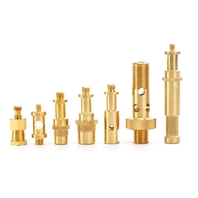


Products Description

Product Function & How It Works
Standard solder pads can weaken under mechanical load, repeated wiring, or field servicing. This terminal solves that problem by providing a robust, threaded fastening point directly on the PCB.
The flat metal base is soldered to the board first, establishing a reliable electrical and mechanical anchor. Once secured, a screw is driven into the threaded post to clamp wire terminals, copper plates, or small busbars tightly against the contact surface. This screw-down method keeps the joint firmly in place during assembly, routine maintenance, and long-term operation, helping to protect the underlying solder connections from stress.
Where It Is Used
You will typically find these power terminals on circuit boards that demand a connection stronger than a conventional solder joint can offer. Common environments include power supply boards, charger modules, inverter circuits, industrial control units, and broader electrical interconnection assemblies.

Customization & Configurable Dimensions
The terminal is not a one-size-fits-all component. Several geometric features can be adapted to align with your specific PCB layout:
Screw position and thread size
Standard offerings cover M4, M5, and M6 threads, with other diameters available on request.
Mounting foot shape
The footprint can be modified to match your hole pattern and board space.
Bending height
The vertical offset is adjustable to accommodate different board stacking or housing requirements.
Contact body width
The conductive cross-section can be tailored to suit current-carrying needs and space constraints.
Material & Surface Finish

The base material is typically high-conductivity brass, with copper alloy specified where the design requires it. For applications where solderability is the top priority, tin plating is the standard finish. When the operating environment calls for different surface characteristics-such as enhanced corrosion resistance or a specific contact interface-nickel plating and other treatment options can be supplied.
To define the exact part, the following specifications are referenced:
Thread size
Screw position
Mounting foot shape
PCB hole spacing
Body width
Bending height
Material thickness
Current requirement
Surface finish
Order quantity
PCB drawing or sample

Suggested Applications
Power supply boards
Inverter boards
Charger modules
Industrial control boards
Electrical connection units
PCB wiring assemblies
How to Request a Quote
For an accurate cost estimate, please share your PCB layout file or a clear sample photograph. The essential details we need are the thread size, required current rating, hole spacing, material thickness, mounting orientation, and expected order quantity.
Simply send your board design or sample image, and we will verify that the screw contact dimensions, foot position, and material thickness match your layout perfectly.
Hot Tags: tin plated brass pcb power terminal, China tin plated brass pcb power terminal manufacturers, suppliers, factory


